High-Speed PCBs
As digital systems push beyond multi-gigabit data rates, high-speed PCBs have become critical for modern electronics from 5G networks to AI accelerators. Building high-speed boards requires precise impedance control, advanced materials, and expert fabrication to minimize signal degradation.
Table of Contents
What are High-Speed PCBs?
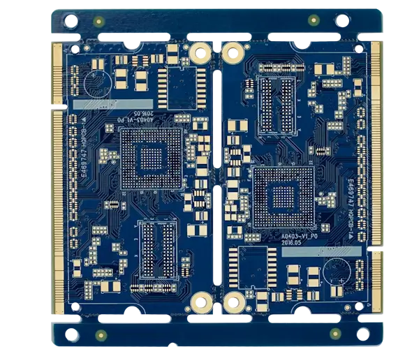
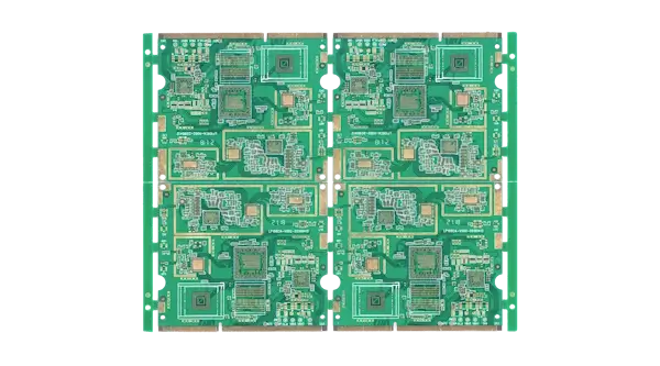
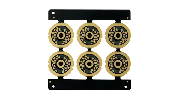
High-speed DDR SDRAM PCB panel
High-speed printed circuit boards are circuit boards that are engineered to process high-speed signals in such a way that maintains signal integrity (SI) and power integrity (PI). High-speed PCBs must take into account the electromagnetic wave behaviour of electrons and consider transmission line effects, electromagnetic interference (EMI) and signal degradation caused by high-frequency operation.
>> Recommend reading: Is Your Design High-Speed or High-Frequency? A Simple Checklist
High-speed design techniques are required when:
The frequency of digital signals exceeds 50-100MHz or when signal rise/fall times are shorter than 1 nanosecond. This includes modern digital interfaces, including USB3.2, HDMI 2.1, PCIe 4.0, DDR5, etc.
The frequency of analog/radio frequency (RF) signals exceeds 300-500 MHz such as Wifi 6, 5G, radar and satellite communications.
| Interface | Version | Max Speed | Applications |
|---|---|---|---|
| USB | USB 3.0 (USB 3.2 Gen 1) | 5 Gbps | External HDDs, flash drives |
| USB 3.2 Gen 2 | 10 Gbps | Fast SSDs, docking stations | |
| USB4 / Thunderbolt 4 | 40 Gbps | High-speed docking, eGPUs | |
| HDMI | HDMI 1.4 | 10.2 Gbps | 1080p @ 120Hz, 4K @ 30Hz |
| HDMI 2.0 | 18 Gbps | 4K @ 60Hz, HDR | |
| HDMI 2.1 | 48 Gbps | 4K @ 120Hz, 8K @ 60Hz | |
| Ethernet | 1 Gigabit (1GbE) | 1 Gbps | Home/small office internet |
| 10 Gigabit (10GbE) | 10 Gbps | Servers, high-speed NAS | |
| 100 Gigabit (100GbE) | 100 Gbps | Data centers, cloud computing | |
| PCIe | PCIe 3.0 | ~8 Gbps per lane | Older GPUs, SSDs |
| PCIe 4.0 | ~16 Gbps per lane | Modern GPUs (RTX 3000), NVMe SSDs | |
| PCIe 5.0 | ~32 Gbps per lane | RTX 4000, next-gen SSDs | |
| RAM (DDR) | DDR4 | ~25 GB/s (total) | Older desktops, laptops |
| DDR5 | ~50 GB/s (total) | New PCs (Ryzen 7000, Intel 12th/13th Gen) |
Despite significant overlap, the techniques and priorities in high-speed digital and analog design differ. To amplify the distinction, analog high-speed boards are often referred to as high-frequency (HF) boards, and digital circuits are referred to as high-speed digital circuits (HSD), highlighting the respective frequency and data-rate dependence. In this discussion, we will focus on high-speed digital circuits unless otherwise specified. For RF circuits, please refer to our high-frequency analog PCBs and materials page.
Challenges of High-Speed PCB Design
High-speed design takes PCB design and engineering to a whole new level. No longer are circuits simply the physical manifestation of a netlist. Trace widths influence more than just current-carrying capacity and electromagnetic wave behaviour dominates every decision. High-speed design is a completely different discipline that flips first-order logic on its head, and while guidelines and best practices for high-speed design are proliferant, so are the myths. Successful high-speed design requires tight collaboration and understanding across design, fabrication and testing teams for optimal results.
PCB Fabricator Services to Optimize Signal Integrity
In addition to diligently following high-speed design practices, there are various ways in which working with your PCB manufacturer can help you achieve signal integrity goals.
Impedance Tuning
One of the most important ways a fabricator can help high-speed designers is by offering impedance control services, including verification, testing and even helping with tuning. For loose requirements, online impedance calculators and datasheets may suffice. However, the impedance of signal traces can be affected by several factors, many of which are beyond the designer's control. PCB manufacturers have better control and understanding of their manufacturing processes and tolerances, and can verify the actual impedance with impedance coupons. A combined approach with cooperation from both the designer and fabricator is the best strategy to maximize success in high-speed designs.
Controlled impedance services and resources to look out for:
Impedance Control Services
A service where you tell your fab house which signals require impedance control and let the fab's engineers modify the trace widths/spacing, taking into account manufacturing tolerances (variations in etching, layer alignment, material consistency, etc.). Impedance test coupons are added to the panel, which replicate the geometry of the target traces and an instrument such as a Time Domain Reflectometer (TDR) is used to confirm the impedance matches target values. There is often an additional charge for this service, but it is an effective way to guarantee impedance compliance for relatively loose tolerances.
Use Standard Stack-ups
No impedance control service? Many quickturn services lack the expertise to provide the impedance control services mentioned above. However, with the necessary data and guarantees, it is perfectly acceptable to fine-tune impedance yourself with results within ±10%, the acceptable range for most consumer electronics.
To save production costs, seek the manufacturer's standard stack-ups and material datasheets for thicknesses, dielectric constants and loss values for impedance calculations. Ensure you are able to guarantee the same stack-up for production. Manufacturers may have multiple default stack-ups and even if a stack-up is considered standard, orders may be pooled with other boards with custom stack-ups to save costs.
Look out for impedance calculator/stack-up selector tools provided by manufacturers that incorporate their available stack-ups and materials.
Build Custom Stack-ups
For more complex structures, support for custom stack-ups with built-in impedance allows you to specify the core/prepreg material and thicknesses to your specifications.
For quickturn services, this option is relatively expensive as it limits pooling options, but it gives maximum control over the PCB's electrical and mechanical properties.
Advanced Manufacturing Support for High-Speed Designs
In ultra-high-speed digital designs, nanosecond/sub-picosecond rise times transition signal behavior into the RF domain, where dispersion, skin effect, and impedance discontinuities dominate signal integrity. High-frequency strategies can be used to mitigate distortion and reduce losses, such as by using substrate materials with exceptionally low loss and stable dielectric constants, smooth copper, backdrilling vias and filling vias. Tighter impedance control, precise trace geometries, material selection and quality control are essential for tight impedance goals within ±5%, common in aerospace, medical, defense and mmWave radar applications.
NextPCB delivers high-performance PCB fabrication with solutions for high-speed and high-frequency designs for various signal integrity requirements. Have our engineers tune your impedance traces to your requirements, use our stack-up selector and impedance calculator tool, or explore our vast range of high-speed laminates and capabilities.
NextPCB High-Speed PCB Manufacturing Capabilities
| Capability | Details |
|---|---|
| Stack-ups | Custom multilayer PCB stack-ups |
| Materials |
High-Speed PCB materials High-Frequency materials |
| Impedance Control Services |
|
| Fabrication techniques |
|
| Industries/Technologies |
|
Get a quote or inquire for more capabilities.
How to choose High-Speed PCB Materials
Beyond PCB design, one of the most important decisions that influences signal integrity is the PCB's substrate material. At higher speeds (~5 GHz), increasing dielectric losses (loss tangent, or Df) dominate, making high-speed/high-frequency materials necessary for the effective preservation of signal integrity. Selecting the right materials and stackup depends on clock speed, frequency range, Df, Dk, thermal and mechanical requirements and budget. For exceptionally low dielectric losses and stable Dk, Rogers and PTFE (Teflon) PCB materials may be preferred for high-speed digital designs as high-frequency effects become significant.
NextPCB offers a wide range of high-speed PCB laminates from trusted brands, suitable for applications spanning consumer electronics to aerospace applications. Get a quote by selecting a material and submitting your request.
NextPCB High-Speed PCB Materials
| Material Code | Brand | Type | Dk | Df | Tg (°C) | Halogen-Free | Datasheet |
|---|---|---|---|---|---|---|---|
| IT-988G SE | ITEQ | 40-56 Gbps | 3.2 | 0.0025 | 190 (DSC) | Yes | IT988GSE.pdf |
| R-5785N/M7N | Panasonic | 40-56 Gbps | 3.3 | 0.002 | 200 (DSC) | No | R5785N(M7N).pdf |
| TU-933 | TUC | 25-40 Gbps | 3.4 | 0.0025 | 170 (TMA) | No | TU933.pdf |
| Tachyon 100G | Isola | 25-40 Gbps | 3.02 | 0.0021 | 215 (DSC) | No | Tachyon100G.pdf |
| IT-968 SE | ITEQ | 25-40 Gbps | 3.3 | 0.0038 | 185 (DSC) | No | IT968SE.pdf |
| R-5785/M7 | Panasonic | 25-40 Gbps | 3.6 | 0.003 | 200 (DSC) | No | R5785(M7).pdf |
| R-5775N/M6N | Panasonic | 25-40 Gbps | 3.4 | 0.004 | 185 (DSC) | No | R5775N(M6N).pdf |
| IT-968 | ITEQ | 10-25 Gbps | 3.7 | 0.0047 | 185 (DSC) | No | IT968.pdf |
| R-5775G/M6G | Panasonic | 10-25 Gbps | 3.6 | 0.004 | 185 (DSC) | No | R5775G(M6G).pdf |
| TU-883 | TUC | 10-25 Gbps | 3.39 | 0.0045 | 170 (TMA) | Yes | TU883.pdf |
| EM-891 | EMC | 10-25 Gbps | 3.6/3.2 | 0.0054/0.0045 | 170 (TMA) | No | EM891.pdf |
| EM-888K | EMC | 10-25 Gbps | 3.2/3.1 | 0.0062/0.0074 | 170 (TMA) | No | EM888K.pdf |
| I-Tera MT40 | Isola | 10-25 Gbps | 3.45 | 0.0031 | 215 (DSC) | No | ITeraMT40.pdf |
| R-5725S/M4S | Panasonic | 5-10 Gbps | 3.8 | 0.007 | 200 (DSC) | No | R5725S(M4S).pdf |
| TU-872 SLK | TUC | 5-10 Gbps | 3.8 | 0.009 | 190 (TMA) | No | TU872SLK.pdf |
| TU-863 | TUC | 5-10 Gbps | 3.9 | 0.0095 | 170 (TMA) | No | TU863.pdf |
| EM-888 | EMC | 5-10 Gbps | 3.7/3.2 | 0.0073/0.0079 | 170 (TMA) | No | EM888.pdf |
| I-Speed | Isola | 5-10 Gbps | 3.64 | 0.0059 | 180 (DSC) | No | ISpeed.pdf |
| IT-958GTC | ITEQ | 5-10 Gbps | 3.7 | 0.007 | 170 | No | IT958GTC.pdf |
| IT-170GRA1 | ITEQ | 1-5 Gbps | 4 | 0.008 | 180 (DSC) | Yes | IT170GRA1.pdf |
| TU-862 HF | TUC | 1-5 Gbps | 4.4 | 0.01 | 170 (TMA) | Yes | TU862HF.pdf |
| Isola-FR408HR | Isola | 1-5 Gbps | 3.68 | 0.0092 | 190 (DSC) | No | IsolaFR408HR.pdf |
| Isola-FR406 | Isola | 1-5 Gbps | 3.93 | 0.0167 | 170 (DSC) | No | IsolaFR406.pdf |
| EM370(Z) | EMC | 1-5 Gbps | 4.2/3.8 | 0.015/0.019 | 180 (TMA) | Yes | EM370(Z).pdf |
| EM828G | EMC | 1-5 Gbps | 3.8/3.3 | 0.011/0.013 | 170 (DSC) | Yes | EM-828G.pdf |
| NP175FM | Nanya | 1-5 Gbps | 3.89 | 0.014 | 170 (DSC) | No | NP175FM.pdf |
Get a quote or inquire for more materials.
Browse Advanced PCB Capabilities at NextPCB
Browse Different PCB Solutions for Every Need
Looking for the right PCB solution? Explore various types of PCBs to find the perfect match for your project.
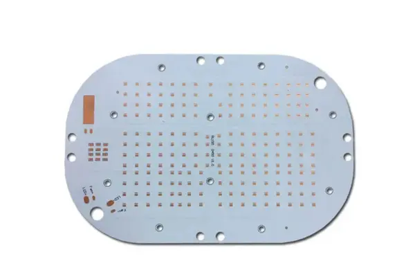
PCBs with aluminum metal core for efficient heat dissipation in high‑power designs.
- - Excellent thermal management and durability
- - Lightweight and cost‑effective
- - Good choice for LED/power electronics
- - Metallic core also helps EMI control
Standard rigid FR4 boards offering stable structure for general electronic systems.
- - Strong mechanical support and heat resistance
- - Supports complex, high‑density layouts
- - Easy for automated assembly
- - Widely used across industries
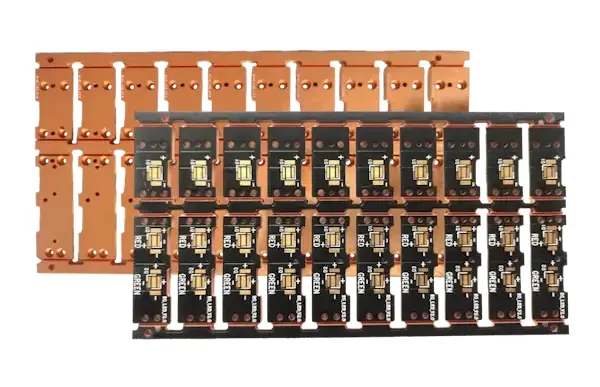
Metal‑core PCB with copper base for superior thermal conductivity and heat spreading.
- - Top thermal performance among metal core PCBs
- - Strong mechanical stability and rigidity
- - Ideal for high‑power/high‑temp boards
- - Can reduce warpage vs aluminum cores
PCBs made with high glass transition temperature (Tg) materials, typically 170°C and above.
- - Enhanced thermal resistance and stability
- - Improved mechanical strength at high temperatures
- - Reduced thermal expansion
- - Better chemical resistance
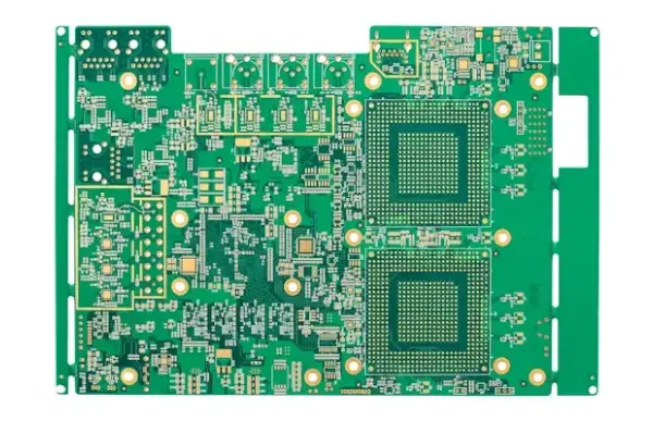
PCBs designed to handle signals in the GHz range with minimal signal loss and distortion.
- - Low dielectric constant (Dk) and dissipation factor (Df) materials
- - Precise impedance control
- - Specialized copper foils with low surface roughness
- - Controlled dielectric thickness
High Density Interconnect PCBs with finer lines, smaller vias, and higher connection density.
- - Microvias (laser-drilled)
- - Finer trace widths and spacing
- - Higher pad density
- - Sequential lamination
- - Any-layer via structures
PCBs manufactured using Rogers Corporation's high-performance laminate materials.
- - Low dielectric loss for high-frequency applications
- - Stable electrical properties over temperature
- - Low moisture absorption
- - Excellent thermal management
PCBs with exceptionally thick copper layers, typically 3 oz or more, for high-current applications.
- - Extremely high current-carrying capacity
- - Enhanced thermal conductivity
- - Ability to withstand repeated thermal cycling
- - Reduced need for external heat sinks
Bendable PCBs made with polyimide or polyester substrates for dynamic or space-constrained designs.
- - High flexibility and bendability (can flex over 200 million cycles)
- - Lightweight and space-saving design
- - Excellent vibration and shock resistance
- - Single-layer, double-layer, or multi-layer
Hybrid circuit boards that combine rigid and flexible substrates into a single integrated assembly.
- - Combines stability with flexibility
- - Eliminates connectors and solder joints between rigid sections
- - Increased reliability with fewer interconnection points
- - Space and weight-saving
Using ceramic substrates like Al₂O₃ and AlN for extreme thermal and electrical performance.
- - Excellent thermal conductivity
- - High-temperature operation
- - Superior electrical insulation and dielectric strength
- - Low thermal expansion coefficient matching semiconductors